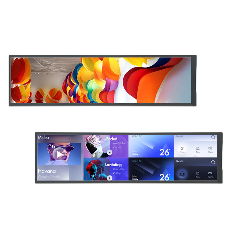
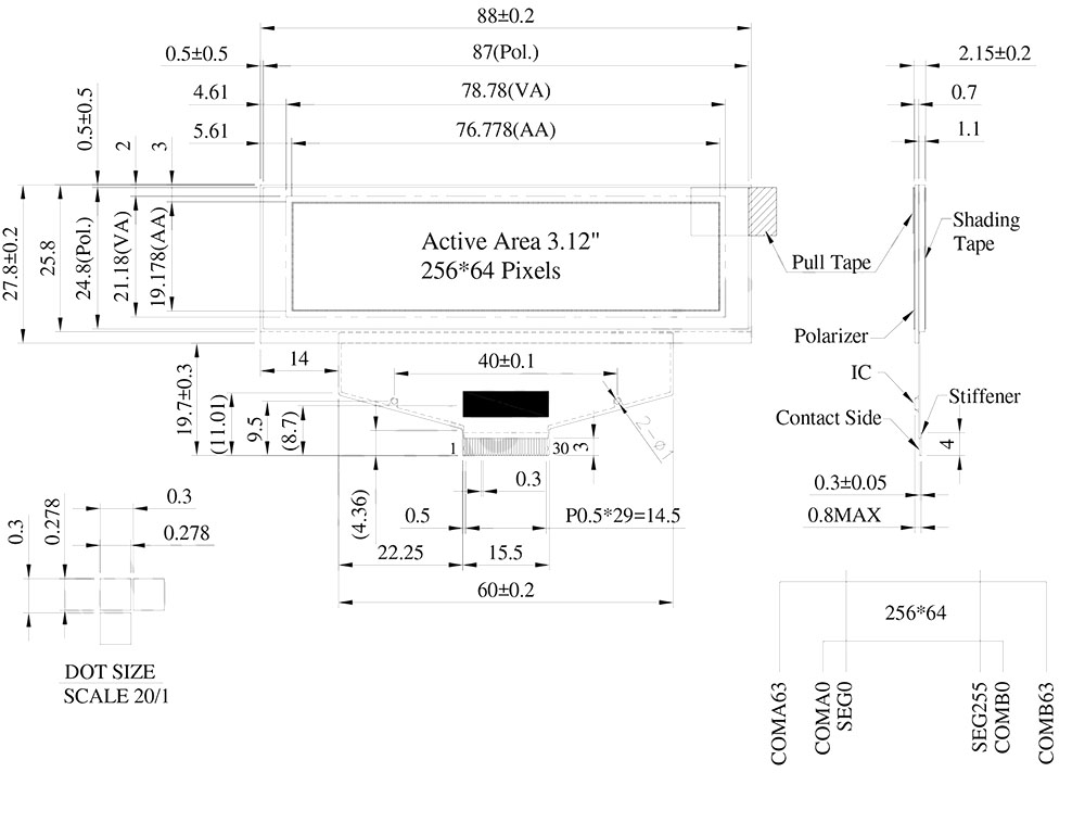
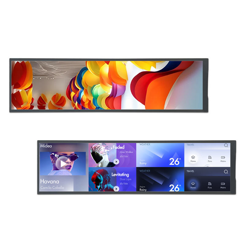
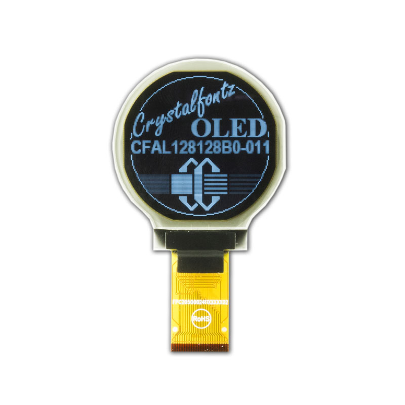
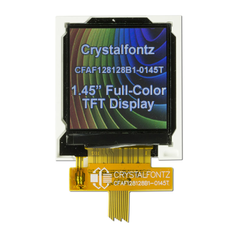
You can rest assured to buy customized COF Color OLED Display from us. The model WEX025664B is a 3.12-inch COF-structured OLED graphic display with a resolution of 256x64 dots. This 3.12" OLED display is equipped with an SSD1322 driver IC, supporting 8-bits 6800/8080, and 3-line/4-line SPI interfaces. It has an outline dimension of 88 x 27.8 mm, with an active area size of 76.778 x 19.178 mm. The display features 4-bits grayscale, and its logic voltage is 2.5V (typical value) with a duty cycle of 1/64. The module can operate at temperatures from -40°C to +80°C, and its storage temperature is from -40°C to +85°C.
You can rest assured to buy customized COF Color OLED Display from us.
The OLED module features a high contrast ratio of 10,000:1, allowing for more vibrant and true-to-life colors, deeper blacks, and brighter whites. This results in enhanced image quality, sharper details, and improved readability, particularly in low-light environments. Additionally, the high contrast ratio contributes to a more immersive viewing experience.
The OLED module is suitable for various applications such as wall/meter devices, home applications, POS systems, Cloud/IoT systems, handheld instruments, intelligent technology devices, energy systems, automotive applications, communication systems, and medical instruments. Customers can upgrade their current applications from traditional STN displays to OLED displays, as the module provides a very wide range of dot pixel formats for OLED solutions.
Additionally, OLED panels with the same dimensions offer a variety of alternatives:
●WEX025664B-CTP series without a metal frame, PCB, and with a CTP touch screen.
●WEN025664B series with a metal frame and PCB.
●WEN025664B-CTP series with a metal frame, PCB, and CTP touch screen.
DRAWING
Data source ref: WEX025664BWPP3N00000
SPECIFICATIONS
Interface Pin Function
Pin Number
Symbol
I/O
Function
1
N.C. (GND)
P
Ground
2
VSS
P
Ground.
3
VCC
P
Power supply for panel driving voltage.
This is also the most positive power voltage supply pin.
4
VCOMH
P
COM signal deselected voltage level.
A capacitor should be connected between this pin and VSS.
5
VLSS
P
Analog system ground pin.
6~13
D7~D0
I/O
Host Data Input/Output Bus
These pins are 8-bit bi-directional data bus to be connected to the microprocessor’s data bus.
When serial mode is selected, D1 will be the serial data input SDIN and D0 will be the serial clock input SCLK.
14
E/RD#
I
Read/Write Enable or Read
This pin is MCU interface input.
When interfacing to a 68XX-series microprocessor, this pin will be used as the Enable (E) signal. Read/write operation is initiated when this pin is pulled high and the CS# is pulled low.
When connecting to an 80XX-microprocessor, this pin receives the Read (RD#) signal. Data read operation is initiated when this pin is pulled low and CS# is pulled low.
When serial mode is selected, this pin must be connected to VSS.
15
R/W#
I
Read/Write Select or Write
This pin is MCU interface input. When interfacing to a 68XX-series microprocessor, this pin will be used as Read/Write (R/W#) selection input. Pull this pin to “High” for read mode and pull it to “Low” for write mode.
When 80XX interface mode is selected, this pin will be the Write (WR#) input. Data write operation is initiated when this pin is pulled low and the CS# is pulled low.
When serial mode is selected, this pin must be connected to VSS.
16
BS0
I
Communicating Protocol Select
These pins are MCU interface selection input. See the following table:
BS:[1:0]
Bus Interface Selection
00
4 line SPI
01
3 line SPI
10
8-bit 8080 parallel
11
8-bit 6800 parallel
Note
(1) 0 is connected to VSS
(2) 1 is connected to VDDIO
17
BS1
18
D/C#
I
Data/Command Control
This pin is Data/Command control pin connecting to the MCU.
When the pin is pulled HIGH, the content at D[7:0] will be interpreted as data.
When the pin is pulled LOW, the content at D[7:0] will be interpreted as command.
19
CS#
I
Data/Command Control
This pin is the chip select input connecting to the MCU. The chip is enabled for MCU communication only when CS# is pulled LOW.
20
RES#
I
This pin is reset signal input.
When the pin is pulled LOW, initialization of the chip is executed.
Keep this pin pull HIGH during normal operation.
21
FR
O
This pin is No Connection pins. Nothing should be connected to this pin. This pin should be left open individually.
22
IREF
I
Current Reference for Brightness Adjustment
This pin is segment current reference pin. A resistor should be connected between this pin and VSS. Set the current lower than 10uA.
23
N.C.
-
Reserved Pin
The N.C. pin between function pins are reserved for compatible and flexible design.
24
VDDIO
P
Power Supply for I/O Pin
It should be matched with the MCU interface voltage level.
25
VDD
P
Power Supply for Core Logic Circuit
Power supply pin for core logic operation. A capacitor is required to connect between this pin and VSS
26
VCI
P
Power Supply for Operation
VCI must always be equal to or higher than VDD and VDDIO.
27
VSL
P
Voltage Output Low Level for SEG Signal
This is segment voltage reference pin.
When external VSL is not used, this pin should be left open.
When external VSL is used, this pin should connect with resistor and diode to ground.
28
VLSS
P
Ground of Analog Circuit
These are the analog ground pins. They should be connected to VSS externally.
29
VCC
P
Power Supply for OLED Panel
These are the most positive voltage supply pin of the chip. They must be connected to external source.
30
N.C. (GND)
P
Ground
General Specification
Item
Dimension
Unit
Dot Matrix
256 x 64 Dots
-
Module dimension
88.0 × 27.8 × 2.15
mm
Active Area
76.778×19.178
mm
Pixel Size
0.278×0.278
mm
Pixel Pitch
0.3×0.3
mm
Display Mode
Passive Matrix
Display Color
Monochrome
Drive Duty
1/64 Duty
Gray Scale
4 bits
IC
SSD1322 (COF)
Interface
6800, 8080, SPI
Size
3.12 inch
Absolute Maximum Ratings
Parameter
Symbol
Supply Voltage for Operation
VCI
Supply Voltage for Logic
VDD
Supply Voltage for I/O Pins
VDDIO
Supply Voltage for Display
VCC
Operating Temperature
TOP
Storage Temperature
TSTG
Electronical Characteristics
Item
Symbol
Condition
Min
Typ
Max
Unit
Supply Voltage for Logic
VDD
-
2.4
2.5
2.6
V
Power Supply for I/O pins
VDDIO
-
1.65
3.0
VCI
V
Low voltage power supply
VCI
-
2.4
3.0
3.5
V
Supply Voltage for Display
VCC
-
11.5
14.5
15
V
High Level Input
VIH
-
0.8×VDDIO
-
VDDIO
V
Low Level Input
VIL
-
0
-
0.2×VDDIO
V
High Level Output
VOH
-
0.9×VDDIO
-
VDDIO
V
Low Level Output
VOL
-
0
-
0.1×VDDIO
V
50% Check Board operating Current
ICC
VCC =12V
-
24
32
mA
VCC =14.5V
-
32
42.5
mA
Hot Tags: COF Color OLED Display, China, Manufacturer, Supplier, Factory, Customized, Quality, Discount, Free Sample
For inquiries about LED display, LCD display, digital color screen or price list, please leave your email to us and we will be in touch within 24 hours.
We use cookies to offer you a better browsing experience, analyze site traffic and personalize content. By using this site, you agree to our use of cookies.Privacy Policy